
Introduction
The construction of urban highway flyovers and elevated road corridors requires structural systems that can safely transfer heavy traffic loads to foundations while maintaining adequate clearance, durability, economy, and traffic flow at grade level. One of the critical components in such structures is the pier cap, which transfers loads from the bridge superstructure to the pier columns or shafts.
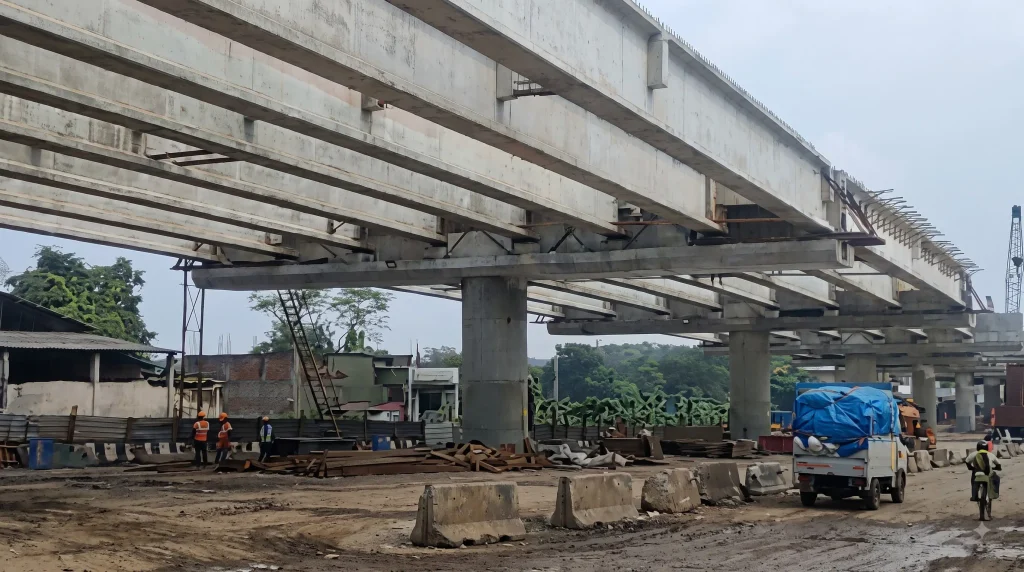
For a four-lane highway flyover, a post-tensioned cantilever pier cap can be an effective structural solution where conventional reinforced concrete pier caps would require excessive depth, reinforcement congestion, or large supporting columns.
A post-tensioned cantilever pier cap is generally constructed using high-strength concrete and prestressing tendons that are tensioned after the concrete reaches the specified strength. The prestressing force introduces beneficial compressive stresses into the concrete and helps control tensile stresses, cracking, and deflection under service loads.
This article explains the structural configuration, design considerations, analysis methodology, construction sequence, and quality-control requirements for a post-tensioned cantilever pier cap supporting a four-lane highway flyover.
1. What Is a Post-Tensioned Cantilever Pier Cap?
A pier cap is a transverse structural member provided at the top of a bridge pier to support the bridge superstructure. It receives concentrated reactions from bearings supporting the bridge girders or deck system and transfers these forces to the pier and foundation.
In a cantilever arrangement, the pier cap projects beyond its supporting pier or column. These projecting portions carry the reactions from the superstructure and behave primarily as cantilevering structural regions.
Post-tensioning is introduced to improve the structural performance of the cap, particularly when the cantilever projections, applied loads or overall geometry make a conventional reinforced concrete solution less efficient.
The principal components include:
- Pier shaft or supporting columns: Transfer the pier-cap forces to the foundation.
- Pier cap concrete section: Provides the main load-resisting structural member.
- Prestressing tendons: Introduce compressive forces to improve flexural and serviceability performance.
- Anchorage assemblies: Transfer prestressing forces into the concrete at tendon ends.
- Conventional reinforcement: Resists tensile forces, shear, bursting, spalling and other local stresses.
- Bearing pedestals: Provide suitable seating and load transfer between the superstructure bearings and pier cap.
- Bearing assemblies: Transfer vertical reactions and, depending on their type and arrangement, horizontal forces and rotations.
The final configuration depends on the number of girders, span arrangement, pier geometry, bearing positions, superstructure alignment and available construction space.
2. Structural Arrangement for a Four-Lane Highway Flyover
A four-lane highway flyover generally carries traffic in two directions or on a divided carriageway, depending on the project configuration. The superstructure may consist of precast prestressed concrete I-girders, post-tensioned box girders, precast segmental construction or another approved bridge system.
The pier-cap arrangement must accommodate the actual bearing positions and transfer the resulting reactions safely to the supporting pier.
A typical structural arrangement consists of the following load-transfer sequence:
Four-lane roadway → Bridge deck and girders → Bearings → Post-tensioned pier cap → Pier shaft or columns → Foundation → Supporting soil or rock.
The pier cap may extend on both sides of a central pier shaft, or it may have an asymmetric arrangement where roadway geometry or site constraints require it.
The important design parameters include:
- Overall pier-cap length and cross-sectional dimensions.
- Cantilever projection beyond the pier support.
- Number, location and spacing of bearing pedestals.
- Vertical and horizontal reactions from the superstructure.
- Prestressing tendon profile, eccentricity and anchorage locations.
- Pier-cap connection geometry and supporting-pier stiffness.
- Construction access, lifting requirements and available headroom.
For a four-lane flyover, the pier cap must be designed for the actual superstructure reactions produced by the governing traffic-loading arrangements. It should not be assumed that all four traffic lanes must always be loaded simultaneously with their maximum design loading; the governing lane-loading arrangements and combinations must be established under the applicable bridge-loading code.
3. Why Use Post-Tensioning in a Cantilever Pier Cap?
Conventional reinforced concrete pier caps can become large and reinforcement-intensive when they support heavy girder reactions over substantial cantilever projections.
Post-tensioning can offer several advantages.
3.1 Improved flexural performance
The prestressing force introduces compression into the concrete, counteracting part of the tensile stresses caused by bending. This can improve crack control and serviceability when the tendon profile and prestressing force are appropriately designed.
3.2 Reduced cracking under service loads
The prestressing force can reduce tensile stress in critical regions, helping control flexural cracking. However, it does not eliminate the need for conventional reinforcement or the verification of service-load stresses.
3.3 Efficient use of structural depth
Post-tensioning may allow a more efficient cross-section than an equivalent conventional reinforced concrete solution. The achievable reduction in depth depends on shear capacity, anchorage requirements, tendon geometry, deflection and other governing design checks.
3.4 Better control of deflection
Prestressing can introduce an upward camber that counteracts part of the downward deformation caused by dead and superimposed loads. Long-term deflection must still account for prestress losses, creep, shrinkage, cracking and sustained loading.
3.5 Potential construction and durability benefits
A well-designed prestressed cap can reduce reinforcement congestion and improve concrete placement. However, the construction method must accommodate tendon ducts, anchorages, stressing equipment, grouting access and inspection requirements.
Post-tensioning is not automatically the most economical solution. A comparison with conventional reinforced concrete and alternative pier-cap arrangements should consider the complete construction process, including temporary supports, equipment, stressing operations and long-term maintenance.
4. Design Loads for a Four-Lane Flyover Pier Cap
The design begins with establishing the complete set of actions transferred from the superstructure and generated within the pier-cap system.
4.1 Dead load
Dead load includes the self-weight of the pier cap, bearing pedestals, permanent structural components and other permanently attached elements. The superstructure’s dead-load reactions must be calculated separately and transferred to the pier cap at the relevant bearing locations.
The cap self-weight should be calculated using the actual proposed geometry and the appropriate material unit weight.
4.2 Superimposed dead load
Superimposed dead load may include:
- Wearing course and pavement layers.
- Crash barriers and parapets.
- Utility services and permanent fixtures.
- Other permanent loads specified in the project design basis.
The distribution of these loads depends on the deck arrangement and the structural analysis of the superstructure.
4.3 Vehicular live load
Traffic loading is a major consideration for a four-lane highway flyover.
The design must consider the applicable vehicular loading classes and lane-loading arrangements specified in the governing bridge-loading code. Depending on the project and applicable provisions, these may include IRC Class 70R and IRC Class A loading.
The analysis should establish the most adverse reactions at each bearing and the corresponding force effects in the pier cap.
Critical considerations include:
- Loading of individual lanes and combinations of lanes.
- Longitudinal positioning of traffic loads to maximize bearing reactions and structural effects.
- Transverse distribution of loads through the deck and girder system.
- Impact or dynamic allowance as applicable.
- Eccentric traffic loading and unequal bearing reactions.
- Braking and other traffic-related horizontal forces.
- Applicable combinations involving traffic, wind and seismic actions.
A four-lane carriageway does not necessarily produce the governing pier-cap effect when every lane is loaded in the same manner. The critical loading pattern must be identified through the prescribed load combinations and influence of each load case.
4.4 Prestressing forces
The prestressing force is an essential design action. Both the initial jacking force and the effective prestressing force after losses must be considered.
Prestress losses may arise from:
- Anchorage seating.
- Friction between tendons and ducts.
- Elastic shortening.
- Concrete creep and shrinkage.
- Relaxation of prestressing steel.
- Other losses applicable to the selected prestressing system and construction sequence.
The tendon profile should be selected to provide a favourable balance between prestressing compression, flexural resistance and the additional forces generated by tendon curvature.
4.5 Horizontal and environmental actions
The pier-cap design should also account for applicable horizontal actions, including:
- Braking and traction forces.
- Wind effects.
- Seismic actions.
- Bearing restraint forces.
- Temperature-related movements and restraint effects.
- Construction-stage forces and temporary eccentricities.
- Other project-specific actions, where relevant.
The transfer of these forces through the bearings, pier cap, pier shaft and foundation must be consistent with the global bridge analysis.
4.6 Load combinations
The governing combinations should be established using the applicable editions of the relevant IRC provisions and project requirements.
Both ultimate and serviceability limit states must be checked. The combinations should cover strength, service stresses, cracking, deflection, stability and construction stages as applicable.
5. Structural Analysis of a Post-Tensioned Cantilever Pier Cap
The analysis method must reflect the actual load path, geometry and stiffness of the pier-cap system.
5.1 Establish the structural model
The structural model should include the pier-cap geometry, support conditions, bearing locations, pier connection and relevant stiffness characteristics.
Depending on the geometry and design complexity, the analysis may use:
- A suitable beam or frame model for preliminary assessment.
- A grillage or three-dimensional frame model where load distribution and torsional effects require consideration.
- A three-dimensional finite-element model for complex geometry, concentrated bearing loads, local stress fields and irregular support conditions.
- A strut-and-tie model for disturbed regions where ordinary beam theory does not adequately represent the force flow.
The selected model must be appropriate for the intended verification and supported by sound engineering assumptions.
5.2 Cantilever bending moment
For a simplified cantilever subjected to a single vertical point load, the bending moment at the support can be expressed as:
[ M = P x L]
where:
- (M) = bending moment at the support.
- (P) = applied point load.
- (L) = distance between the point load and the support reference section.
For a distributed load, the bending moment must be calculated from the relevant load distribution and its lever arm.
These expressions are useful for conceptual understanding only. A real pier cap may experience multiple concentrated reactions, transverse bending, torsion, load redistribution and complex local effects. Its design actions should be obtained from the complete structural model and the applicable design provisions.
5.3 Shear force and local force transfer
High shear forces can develop near the pier support and bearing locations. The designer should evaluate the critical sections and load-transfer regions, including:
- One-way shear.
- Local bearing stresses.
- Anchorage-zone stresses.
- Potential diagonal cracking.
- Bursting and spalling forces.
- Interface shear and force transfer at the pier-cap connection.
The shear-resisting mechanism may include concrete compression fields, conventional reinforcement and prestressing effects where these are explicitly permitted by the governing design provisions.
5.4 Torsion and transverse effects
A four-lane flyover may have unequal bearing reactions because of eccentric live loading, curvature, skew, varying girder spacing or asymmetric geometry.
These effects can introduce torsion and transverse bending into the pier cap. A simplified two-dimensional cantilever analysis may therefore be insufficient for the final design.
The analysis should establish the relevant three-dimensional load effects and provide appropriate reinforcement and prestressing arrangements.
6. Preliminary Design of the Prestressing Tendons
Tendon design is one of the most important aspects of a post-tensioned cantilever pier cap.
6.1 Tendon profile
The tendon profile should be selected based on the bending-moment distribution, section geometry, anchorage arrangement and construction feasibility.
The tendon eccentricity relative to the section centroid affects the moment generated by prestressing.
For a simplified section, the prestressing moment can be expressed as:
[ Mp = Pe . e ]
where:
- (M_p) = moment associated with the prestressing force.
- (P_e) = effective prestressing force after applicable losses.
- (e) = tendon eccentricity relative to the section centroid.
The sign and structural effect of this moment depend on the tendon position and the adopted sign convention.
The final tendon profile must also consider curvature forces, duct clearances, minimum bend radii, friction losses, anchor locations and local reinforcement requirements.
6.2 Number and arrangement of tendons
The required number and arrangement of tendons should be determined through structural design rather than assumed from the number of traffic lanes.
The design process should consider:
- Governing ultimate bending and shear effects.
- Service-load concrete stresses.
- Prestress losses and effective force.
- Tendon stress limits at jacking and in service.
- Anchorage-zone and local bursting requirements.
- Fatigue and other relevant checks where required.
- Duct spacing, concrete cover and reinforcement congestion.
- Construction access and the proposed stressing sequence.
Tendon groups should be arranged to provide a suitable load path while allowing adequate space for conventional reinforcement and proper concrete placement.
6.3 Anchorage zones
The concentrated prestressing force transferred through an anchorage creates a complex local stress field.
The anchorage zone must be designed for the applicable bursting, spalling and splitting effects, together with local bearing stresses. Suitable confinement and anchorage-zone reinforcement should be provided in accordance with the prestressing system requirements and the governing design provisions.
Particular attention is required where anchorages are located close to the edge of the pier cap or near the pier-cap connection.
7. Conventional Reinforcement Requirements
Post-tensioning supplements rather than universally replaces conventional reinforcement.
The reinforcement layout should address the following requirements.
7.1 Flexural reinforcement
Provide the required conventional reinforcement for ultimate resistance, crack control, local force transfer and other applicable design requirements.
The reinforcement must be compatible with the prestressing system and the calculated stress distribution.
7.2 Shear reinforcement
Stirrups, links or other specified shear reinforcement must be designed for the governing shear effects and relevant code requirements.
Reinforcement congestion should be assessed at the pier support, bearing pedestals and tendon anchorage regions.
7.3 Anchorage-zone reinforcement
Provide designed reinforcement to resist the local tensile forces generated by prestressing anchorages. The layout should be coordinated with the anchorage manufacturer’s requirements and the approved prestressing-system details.
7.4 Confinement and connection reinforcement
The pier-cap-to-pier connection requires adequate reinforcement for the transfer of forces between the cap and its supporting element.
Depending on the structural configuration, this may include confinement reinforcement, interface reinforcement, continuity reinforcement and reinforcement designed using strut-and-tie principles.
7.5 Reinforcement around bearing pedestals
Bearing pedestals experience concentrated vertical reactions and potentially horizontal forces.
Their design should address local bearing, splitting, bursting, pedestal stability, reinforcement anchorage and load transfer into the pier cap.
Reinforcement drawings should show bar sizes, spacing, development lengths, laps where permitted, cover and clearances around ducts and anchorages.
8. Construction Methodology
The construction sequence should be selected during design because temporary conditions can govern the structural response of a cantilever pier cap.
Step 1: Construct the pier shaft or supporting columns
Construct the pier shaft or columns in accordance with the approved drawings and method statement. Verify the location, reinforcement, concrete strength, top elevation and connection details before proceeding with the cap.
Step 2: Install formwork and temporary supports
Provide a stable formwork and support system designed for the wet-concrete load, reinforcement, prestressing ducts, construction equipment and other applicable temporary loads.
Where a cantilever pier cap is constructed using staged support arrangements, the temporary system must safely resist the relevant construction-stage forces.
Step 3: Fix reinforcement and prestressing ducts
Install conventional reinforcement and tendon ducts in the approved sequence. Check duct alignment, tendon profile, duct supports, anchorage locations, concrete cover and clearances.
The ducts must be securely fixed to prevent movement during concrete placement and vibration.
Step 4: Inspect and cast the concrete
Before casting, inspect the reinforcement, ducts, anchorages, formwork and embedded items.
Place and compact the specified concrete to avoid honeycombing, voids and segregation, particularly in congested anchorage zones.
Concrete placement should be coordinated with the approved construction-joint arrangement and the requirements for the selected prestressing system.
Step 5: Cure the concrete and verify strength
Carry out curing in accordance with the approved specifications. Concrete must achieve the specified minimum strength required before stressing.
The decision to commence stressing should be based on the required strength verification and the approved stressing procedure, not merely on the number of days elapsed after casting.
Step 6: Stress the tendons
Stress the tendons using calibrated jacks and the approved stressing sequence. Record the specified jacking force, measured elongation, actual elongation, pressure readings, anchorage seating and any deviations.
The measured tendon elongations should be compared with theoretical values calculated using the approved tendon geometry and prestressing parameters.
Any discrepancy beyond the specified acceptance limits should be investigated and resolved before proceeding.
Step 7: Grout the tendon ducts
For bonded post-tensioning systems, grout the ducts using the approved grout and procedure after the prescribed stressing and inspection requirements have been met.
Verify grout preparation, flow characteristics, filling and venting procedures, and records of grouting operations. Particular care is required to ensure complete filling of the ducts and appropriate treatment of vents and anchorages.
The grouting requirements for the selected system must be followed in accordance with the approved specifications.
Step 8: Remove temporary supports in the approved sequence
Temporary supports should be removed only after the specified strength, prestressing and construction-stage requirements have been satisfied.
The release sequence must be consistent with the structural design and method statement to avoid unintended redistribution of forces or excessive deflection.
Step 9: Install bearings and erect the superstructure
Verify bearing positions, pedestal elevations, bearing orientation, seating surfaces and installation tolerances.
The superstructure should be erected in the approved sequence, with due consideration of temporary stability and the loads imposed on the pier cap during girder placement.
Step 10: Complete inspection and documentation
Complete the required inspections, stressing records, grouting records, material certificates, concrete test results and as-built documentation.
Any nonconformity affecting structural performance must be evaluated and resolved through the approved quality-control process.
9. Quality-Control and Inspection Checklist
A comprehensive inspection process is essential for the long-term performance of a post-tensioned pier cap.
| Inspection item | Key requirement |
|---|---|
| Concrete | Verify grade, workability, placement, curing and specified strength |
| Reinforcement | Check bar sizes, spacing, cover, anchorage and congestion |
| Prestressing ducts | Verify alignment, continuity, support and condition |
| Anchorages | Check location, orientation, bearing and reinforcement |
| Tendon stressing | Verify calibrated equipment, jacking force and elongation |
| Prestress losses | Confirm calculations and effective prestressing assumptions |
| Grouting | Verify materials, procedure, records and duct filling |
| Bearing pedestals | Check dimensions, elevations, reinforcement and seating |
| Geometry | Confirm cap dimensions, alignment, levels and tolerances |
| Construction stages | Verify compliance with the approved sequence |
| As-built records | Maintain inspection, testing and approval documentation |
The inspection and acceptance requirements should be defined in the approved project specifications and method statements.
10. Common Design and Construction Mistakes
The following issues should be avoided during the design and execution of a post-tensioned cantilever pier cap.
1. Assuming uniform load distribution across four lanes
The governing effects depend on the superstructure, bearing positions and prescribed traffic-loading arrangements. Actual bearing reactions should be used in the pier-cap analysis.
2. Ignoring three-dimensional behaviour
Eccentric reactions, skew and unequal girder loads can generate torsion and transverse bending. These effects should be included where relevant.
3. Selecting tendons before establishing the force distribution
Tendon quantity and profile should follow the structural analysis, stress checks and anchorage requirements rather than being chosen solely from geometric convenience.
4. Neglecting anchorage-zone design
Local stresses at tendon anchorages can be significant. Anchorage-zone reinforcement and concrete dimensions require specific verification.
5. Treating the cap as an ordinary slender beam
Deep or heavily loaded pier caps may contain disturbed regions in which conventional beam assumptions do not adequately capture the force flow. Suitable strut-and-tie or other appropriate analysis methods may be required.
6. Ignoring temporary construction stages
Formwork removal, tendon stressing, girder erection and changes in support conditions can produce critical intermediate load cases.
7. Inadequate grouting and corrosion protection
Poor duct filling or defective protection details can compromise the durability of prestressing steel. Grouting and anchorage protection require controlled execution and documentation.
8. Inadequate coordination between structural design and reinforcement detailing
Clashes between tendons, ducts, anchorages, links and bearing reinforcement can obstruct concrete placement and affect structural performance. Detailed coordination should be completed before issuing construction drawings.
11. Applicable Indian Codes and Technical References
For a highway flyover in India, the design team should identify the applicable editions, amendments and project-specific requirements of the following documents.
- IRC:6 — Loads and Load Combinations for Road Bridges: For applicable traffic loading, impact and dynamic effects, other bridge loads and load combinations.
- IRC:112 — Code of Practice for Concrete Road Bridges: For concrete bridge design, including relevant ultimate and serviceability limit-state requirements.
- IRC:18 — Design Criteria for Prestressed Concrete Road Bridges: Consult the applicable edition and its current status for the provisions relevant to the selected prestressed bridge system.
- IRC:78 — Standard Specifications and Code of Practice for Road Bridges: Foundations and Substructure: For relevant foundation and substructure requirements.
- MoRTH Specifications for Road and Bridge Works: For applicable materials, construction, prestressing, grouting, workmanship and quality-control requirements.
- Project-specific specifications and approved prestressing-system documentation: For system-specific stressing procedures, equipment calibration, anchorage details, grouting and acceptance criteria.
The designer should confirm the current applicability and scope of each reference before using it. The list above is a starting point, not a substitute for a project-specific code register. Applicable seismic, wind, bearing and other specialist provisions must also be included where relevant.
12. Design Deliverables for a Post-Tensioned Pier Cap
A complete design submission should contain sufficient information for independent review, construction and inspection.
Typical deliverables include:
- General arrangement drawing showing the pier cap, supporting pier and bearing locations.
- Design basis, geometry, material properties and governing code register.
- Superstructure bearing reactions and relevant load-combination summaries.
- Structural analysis model description, assumptions and governing force effects.
- Ultimate strength and serviceability design calculations.
- Prestressing calculations, tendon profiles, losses and stressing requirements.
- Anchorage-zone and local bearing-zone design checks.
- Conventional reinforcement calculations and detailed reinforcement drawings.
- Construction-stage analysis and temporary support requirements where applicable.
- Stressing, grouting, inspection and quality-control method statements.
The submission should clearly distinguish design assumptions from verified project data and should include the required independent checks and approvals.
Frequently Asked Questions
1. Why is post-tensioning used in a cantilever pier cap?
Post-tensioning can improve flexural performance, control service-load cracking and deflection, and help achieve an efficient structural depth where a conventional reinforced concrete solution would be less suitable.
2. Is a post-tensioned pier cap suitable for every four-lane flyover?
No. Its suitability depends on the span arrangement, bearing reactions, cantilever length, pier geometry, structural depth, construction method, cost and maintenance requirements.
3. How are prestressing tendons designed for a cantilever pier cap?
Tendon design is based on the governing structural actions, service stresses, ultimate resistance, prestress losses, tendon eccentricity, anchorage requirements and construction constraints. The final arrangement requires project-specific calculations.
4. Which Indian codes are relevant to a post-tensioned highway pier cap?
IRC:6, IRC:112, the applicable provisions of IRC:18, IRC:78 and the relevant MoRTH specifications are important starting references. The current editions, amendments and project requirements must be verified.
5. What is the most critical construction stage?
There is no universally critical stage. Concrete casting, tendon stressing, temporary-support removal and girder erection can each govern different aspects of the design. All relevant stages must be assessed.

D Singha is a Civil Engineer with expertise in bridge design, structural engineering, and infrastructure projects. He shares insights on engineering, construction practices, technology, and professional development.